Build a USB-C Push-to-Talk Microphone
A handheld mic for your computer that stays muted by default and only passes your voice while you hold a trigger button. A handful of parts, one USB-C cable, no SD card, no drivers.
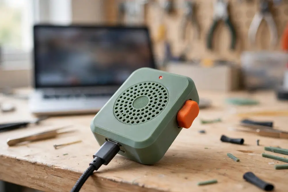 What you are aiming for: a small handheld unit with a mic grille, a chunky side trigger, an LED that lights while you talk, and a single USB-C cable to the computer. Illustration.
About $15-20 CAD in parts
One afternoon breadboard version
Beginner first-project friendly
No SD card audio streams live to the PC
How it works, in one breath
You talk into a tiny digital microphone. A small computer chip (the microcontroller) converts that sound into a stream of numbers and sends it over USB to your laptop, which sees it as an ordinary microphone. The chip checks the trigger button thousands of times per second: if you are not holding it, the chip sends digital silence instead of your voice. That one decision - real audio or silence - is the whole push-to-talk trick.
1. Microphone INMP441 hears sound and outputs digital audio samples
→
2. Microcontroller XIAO ESP32-S3 reads samples and checks the trigger
→
3. USB-C cable Carries power to the device and audio to the computer
→
4. Your computer Sees a normal USB microphone in Discord, Zoom, and so on
This guide assumes you have never touched electronics. Every new term is defined the first time it appears, every procedure is numbered, and the classic beginner mistakes are flagged before you can make them. If you can install software and plug in a cable, you can do the breadboard version of this build. Soldering only appears at the very end, when you make the prototype permanent.
1
Hardware concepts, from zero
Seven short sections carry the whole build. Read this page once now; come back to it whenever a later step uses a word you do not recognise.
Microcontroller
A microcontroller is a complete tiny computer on one chip: processor, memory, and input/output pins. It runs exactly one program, which you write, and it starts that program the instant it gets power. Your laptop runs many programs at once and boots an operating system; the ESP32-S3 on the XIAO board runs your one microphone program, forever, in a loop. In this build the microcontroller is the traffic cop between the microphone and the computer.
GPIO pin
GPIO stands for General-Purpose Input/Output. A GPIO pin is a metal contact on the chip that your program can either read (is a button pressed? is voltage present?) or ** write** (turn an LED on or off). Each pin has a number, like GPIO 4. Confusingly, the XIAO board also prints friendlier labels on its edge - D1, D2, D3 - and D3 is the same physical pin as GPIO 4. This guide always gives both, for example “D3 (GPIO 4)”. The label on the board is what you wire to; the GPIO number is what you type in code.
Breadboard and jumper wires
A solderless breadboard is a plastic grid of holes with hidden metal strips underneath. Holes in the same row of five are secretly connected, so anything plugged into the same group of five touches electrically. You push component legs and wires in, pull them out, and rearrange freely - no soldering, nothing permanent. Jumper wires are short pre-made wires with pins on the ends, used to connect points on the breadboard. Think of the breadboard as a scratch pad for circuits and jumper wires as the pencil lines.
Voltage, ground, and 3V3 versus 5V
Circuits need a complete loop: power flows out of a positive pin, through the part, and back to ground (GND), which is the 0-volt reference. The XIAO offers two power pins: 5V (straight from USB) and 3V3, meaning 3.3 volts. The INMP441 microphone is a 3.3-volt part. Feed it 5 volts and you can permanently damage it. Rule for this whole build: ** the mic only ever touches the pin labelled 3V3**.
2
More concepts: sound, USB, and software
I2S - how the mic sends sound
I2S (pronounced “eye-two-ess”, short for Inter-IC Sound) is a simple digital language for moving audio between chips. It uses three wires. ** SCK** is a clock: a steady tick, like a metronome, that tells both sides when each bit of data is valid. ** WS** (word select) marks the boundary between left-ear and right-ear samples. ** SD** is the actual data: the sound itself, as a stream of numbers, 16,000 times per second in this build. The INMP441 is used because it speaks I2S natively - the sound leaves the mic already digitised, so there is no analogue noise to amplify and no extra amplifier chip to wire up. One quirk: the mic can pretend to be the left ear or the right ear. Its ** L/R pin chooses**. Wiring L/R to GND makes it the left channel, and the code in this guide listens to the left channel, so L/R must go to GND.
USB Audio Class - why no drivers are needed
USB devices introduce themselves to a computer by category, called a class. Keyboards use the Human Interface class; thumb drives use Mass Storage. USB Audio Class (often shortened to UAC) is the category for microphones and speakers. Windows, macOS, and Linux all ship with a built-in UAC driver, so when your finished device announces “I am a microphone”, the computer simply believes it. It appears in sound settings next to your headset, with no downloads. That is the entire trick behind “plug it in and it just works” USB headsets, and this project borrows it.
Firmware, flashing, and the serial monitor
The program that lives on a microcontroller is called firmware - software, but baked into the device. Putting it there is called ** flashing** (or uploading): your computer sends the compiled program down the USB cable and the chip stores it in flash memory, where it survives unplugging. In the Arduino IDE, flashing is one click on the Upload arrow. The ** serial monitor** is a text window in the IDE that shows messages your program prints for you (for example, “button pressed” or the current sound level). It is your main debugging tool: when something misbehaves, the serial monitor is how the chip tells you what it is seeing.
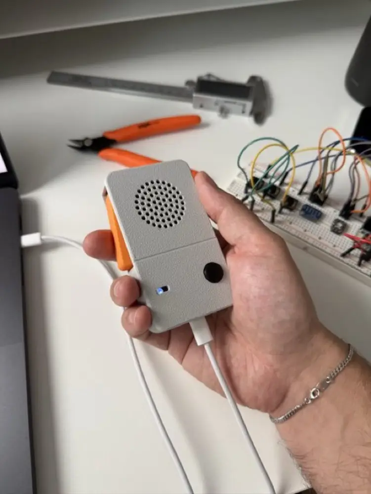 The inspiration: a handheld recorder-style gadget with a big side trigger. Our version keeps the trigger and the handheld shape, but throws away the recorder - it is purely a live microphone for the computer. Photos you supplied.
3
Parts, tools, and installing the software
What to buy
| Part | What it is | Why | Approx. |
|---|---|---|---|
| Seeed XIAO ESP32-S3 | A microcontroller board the size of a postage stamp, with a USB-C socket | The brain. Its ESP32-S3 chip can act as a USB audio device natively - the key requirement | $12-18 |
| ** INMP441 microphone module** | A small breakout board carrying the INMP441 digital mic chip, with 6 pins | Hears the sound and outputs it digitally over I2S | ~$3 |
| ** Tactile pushbutton** | A clicky momentary button (on only while pressed) | The push-to-talk trigger | in a kit |
| ** Red LED + 220 ohm resistor** | A light-emitting diode and a current-limiting resistor | Lights while you are live; the resistor stops the LED burning out | in a kit |
| ** Breadboard + jumper wires** | Solderless prototyping board and pre-made wires | Lets you build and fix the circuit with zero soldering | ~$5-10 |
| ** USB-C data cable** | Must carry data, not just power | Flashes the firmware and carries audio. A charge-only cable will silently fail - see page 6 | you own one |
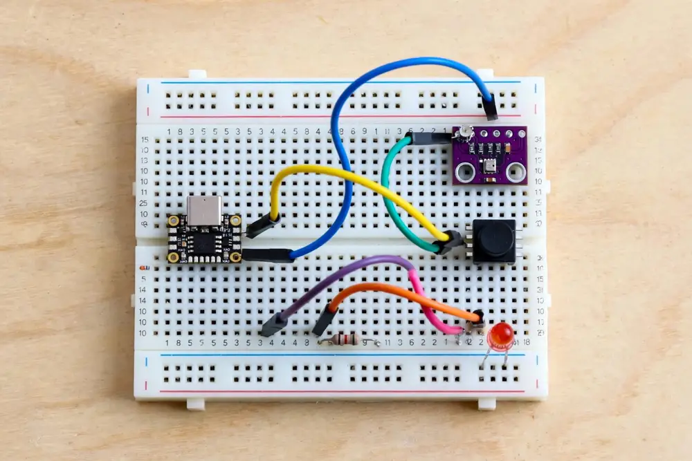 The breadboard prototype: XIAO, microphone module, trigger button, and LED with resistor. Illustration - wire from the table on the next page, not this picture.
Install the Arduino IDE and ESP32 support
The Arduino IDE (Integrated Development Environment) is the free program you write and flash code in. Step 3 below teaches it about ESP32 chips - do not skip it.
- Download the Arduino IDE 2.x installer for your operating system from arduino.cc and install it like any other app.
- Open the IDE. Go to File > Preferences (on macOS, ** Arduino IDE > Settings**).
- Find the field labelled ** Additional boards manager URLs** and paste in this address:
https://raw.githubusercontent.com/espressif/arduino-esp32/gh-pages/package_esp32_index.jsonthen click OK. - Open ** Tools > Board > Boards Manager**, search for ** esp32**, and install the package by Espressif Systems. This is a large download; give it a few minutes.
- Plug the XIAO into your computer with the USB-C data cable.
- Set ** Tools > Board > esp32 > XIAO_ESP32S3**, and set ** Tools > Port** to the new port that appeared when you plugged in.
- Prove the setup works: open ** File > Examples > 01.Basics > Blink** and click the Upload arrow (top left). If the board’s LED blinks afterwards, your toolchain is healthy.
4
Wire it on the breadboard
Unplug the USB cable while wiring - never rearrange wires on a powered board. Push each jumper wire into the breadboard row that shares a strip with the pin it serves. Ten connections in total:
| From | To (XIAO pin) | Wire job |
|---|---|---|
| INMP441 ** VDD** | 3V3 | Power for the mic - 3.3 volts, never 5V |
| INMP441 ** GND** | ** GND** | Ground return |
| INMP441 ** L/R** | ** GND** | Tells the mic “you are the left channel” |
| INMP441 ** SCK** | ** D4 (GPIO 5)** | I2S clock - the metronome tick |
| INMP441 ** WS** | ** D3 (GPIO 4)** | I2S word select - left/right marker |
| INMP441 ** SD** | ** D5 (GPIO 6)** | I2S data - the sound itself |
| Button leg 1 | ** D1 (GPIO 2)** | Trigger input |
| Button leg 2 | ** GND** | Pressing connects D1 to ground |
| LED long leg (+) | 220 ohm resistor, then ** D8 (GPIO 7)** | Live indicator |
| LED short leg (-) | ** GND** | Ground return |
** INMP441**microphone - VDD, GND, L/R, SCK, WS, SD
→
** XIAO ESP32-S3**D3 WS - D4 SCK - D5 SD - D1 button - D8 LED
→
** TRIGGER + LED**button to D1 and GND; LED on D8 via 220 ohm
Sound flows left to right: microphone, to chip, to computer over the USB-C cable. Power (3V3 and GND) comes from the same cable.
** Beginner mistake 1 - 5V kills the mic.** The XIAO has a pin labelled 5V right next to 3V3. The INMP441 accepts at most 3.3 volts. Double-check VDD goes to 3V3 before every power-up.
** Beginner mistake 2 - leaving L/R unconnected.** A floating L/R pin picks up electrical noise and the mic flips channels randomly or goes silent. L/R must be tied to GND (left channel). Do not copy classic-ESP32 wiring diagrams from the internet - their GPIO numbers do not exist on the ESP32-S3.
** Beginner mistake 3 - button without a pull-up.** A GPIO input left unconnected “floats” and reads random presses. The firmware turns on the chip’s internal pull-up resistor, which holds D1 HIGH until your button drags it to GND. That is why pressed reads as LOW in the code - and why the button needs no external resistor.
5
Firmware step 1: prove the microphone works
Never debug two things at once. This first program only checks the mic and prints the sound level as numbers. A sketch (the Arduino word for a program) has two parts: setup() runs once at power-on, and loop() repeats forever.
// Mic test: prints the sound level to the Serial Monitor
#include
I2SClass I2S;
#define PIN_SCK 5
#define PIN_WS  4
#define PIN_SD  6

void setup() {
  Serial.begin(115200);
  I2S.setPins(PIN_SCK, PIN_WS, -1, PIN_SD);
  if (!I2S.begin(I2S_MODE_STD, 16000,
                 I2S_DATA_BIT_WIDTH_32BIT,
                 I2S_SLOT_MODE_MONO, I2S_STD_SLOT_LEFT)) {
    Serial.println("I2S failed to start - check wiring");
    while (true) { }
  }
  Serial.println("Mic ready - talk, whistle, tap the module");
}

void loop() {
  int32_t samples[64];
  size_t n = I2S.readBytes((char*)samples, sizeof(samples));
  long peak = 0;
  for (int i = 0; i > 14;
    if (v  peak) peak = v;
  }
  Serial.println(peak);
  delay(50);
}
Flash it (upload the firmware)
- Paste the sketch into a new Arduino IDE window and save it as
mic-test. - Confirm the board is XIAO_ESP32S3 and the port matches the XIAO (page 4, step 6).
- Click the right-arrow ** Upload** button. The IDE compiles the code (translates it into chip instructions) and flashes it.
- Wait for the words ** Done uploading**. The board restarts itself and begins running your program.
Open the serial monitor and test
- Click the magnifying-glass icon (top right) to open the Serial Monitor.
- Set the baud rate (bits per second - both ends must agree) to 115200, matching the code.
- You should see “Mic ready”, then a stream of numbers. Quiet room: small numbers. Talk, whistle, or tap the mic module: big numbers.
- If the numbers stay near zero, do not go on - use the troubleshooting table on the last page.
** Beginner mistake 4 - a charge-only USB-C cable.** Cheap cables carry power but no data: the board lights up but no port appears in the IDE. If a cable can move phone photos, it can flash firmware.
6
Firmware step 2: add USB audio and the trigger
Your board can introduce itself to the computer as a USB Audio Class microphone. Writing that USB plumbing from scratch is beyond a first project, so start from a working open-source example and add your trigger logic to it.
- Download the example project: ** github.com/probudhabishayee/inmp441-with-esp32-s3-usb-microphone** (a one-channel USB microphone built on exactly your mic and chip family). Open its sketch in the Arduino IDE.
- Find its pin definitions and change them to yours: SCK = 5, WS = 4, SD = 6. Its defaults will not match your wiring.
- Add the three pieces below: the pin definitions near the top, the two
pinModelines insidesetup(), and the gate inside the loop where the example already copies microphone samples towards USB. - Before uploading, set ** Tools > USB Mode** options as the example’s README directs for USB audio, then Upload as before.
// --- add near the top of the sketch ---
#define PIN_BUTTON 2   // D1: the trigger
#define PIN_LED    7   // D8: live light

// --- add inside setup() ---
pinMode(PIN_BUTTON, INPUT_PULLUP);  // idle = HIGH, pressed = LOW
pinMode(PIN_LED, OUTPUT);

// --- the push-to-talk gate, where samples are sent to USB ---
bool talking = (digitalRead(PIN_BUTTON) == LOW);
digitalWrite(PIN_LED, talking ? HIGH : LOW);
if (talking) {
  sendToUSB(micSamples, count);     // your voice
} else {
  sendSilenceToUSB(count);          // zeros: digital mute
}
That if is the product. Because the device sends silence rather than stopping, the computer never sees the microphone vanish - apps stay happy, with no click or pop when you press. Two refinements for later: ignore button changes shorter than about 20 milliseconds (mechanical buttons “bounce”), and keep 16,000 samples per second, which is plenty for voice.
** Honest caveat.** The Arduino-ESP32 USB stack changes between releases, so a year-old example may need small fixes to compile on the current core. Fix the first compile error at the top of the list, not the whole cascade. If the Arduino path fights you for more than an evening, Espressif’s official ESP-IDF tusb_audio example does the same job; the gate code above drops in unchanged.
Test it on your computer
- Plug the breadboard build into the computer and open sound input settings (Windows: Settings > System > Sound; macOS: System Settings > Sound).
- Select the new USB microphone. Watch the input level meter: it should sit at zero while you make noise near the mic.
- Hold the trigger and talk. The meter moves, the LED lights. Release: instant silence, LED off. That is the whole feature working.
- Point Discord, Zoom, or a voice recorder at the new mic and record a sentence both ways.
7
Make it permanent, and fix what breaks
From breadboard to handheld
- Solder the header pins to the XIAO and the mic module (big, forgiving joints - good first soldering practice). Plug them back into the breadboard and re-test before changing anything else.
- Transfer the circuit to a small piece of perfboard, soldering each jumper wire’s path exactly as the breadboard had it. Re-test after every few joints, not at the end.
- Measure the assembly with calipers and model a two-part case around it: mic hole over the INMP441’s sound port (the tiny hole in the chip - block it and you record muffled nothing), a side window for the trigger button, a pinhole for the LED, and the USB-C socket exposed at the base.
- Print the case, assemble, and do the page-7 sound-settings test one last time in its final form.
Troubleshooting
| Symptom | Likely cause | Fix |
|---|---|---|
| No port appears when plugged in | Charge-only USB-C cable, or wrong port selected | Use a known data cable; re-check Tools > Port |
| Serial monitor shows gibberish | Baud rate mismatch | Set the monitor to 115200, matching Serial.begin |
| Mic level always zero | L/R floating, or SCK/WS swapped | L/R must touch GND; re-check the wiring table wire by wire |
| Mic worked, then died | VDD was connected to 5V | Power the mic from 3V3 only; a 5V-fed INMP441 may need replacing |
| Button seems to press itself | No pull-up, so the input floats | Use INPUT_PULLUP and wire the button to GND |
| Button works backwards | Normal with a pull-up | Pressed reads LOW - that is correct; keep the code as written |
| Audio stutters at talk start | Button bounce | Ignore changes shorter than about 20 ms in the loop |
| Computer shows the mic but apps stay silent | App is still using your old microphone | Select the USB mic inside the app as well as the OS |
| Upload fails partway | Board not in download mode | Hold the XIAO’s BOOT button while clicking Upload, release when it starts |
Where to go next
- ** Battery version:** the XIAO has a built-in LiPo charger - add a small battery and the same hardware becomes untethered between charges.
- ** Fancier trigger:** a capacitive touch pad, or a toggle mode (press once to talk, press again to mute) once the momentary trigger feels natural.
Sources and starting points: the USB-audio base example at github.com/probudhabishayee/inmp441-with-esp32-s3-usb-microphone; INMP441 wiring and pin behaviour as documented in Random Nerd Tutorials’ ESP32 INMP441 guide (randomnerdtutorials.com); XIAO ESP32-S3 pin mapping (D1 = GPIO 2, D3 = GPIO 4, D4 = GPIO 5, D5 = GPIO 6, D8 = GPIO 7) per Seeed Studio’s XIAO ESP32S3 documentation. Prices are approximate Canadian-dollar orientation figures, not quotes.
8